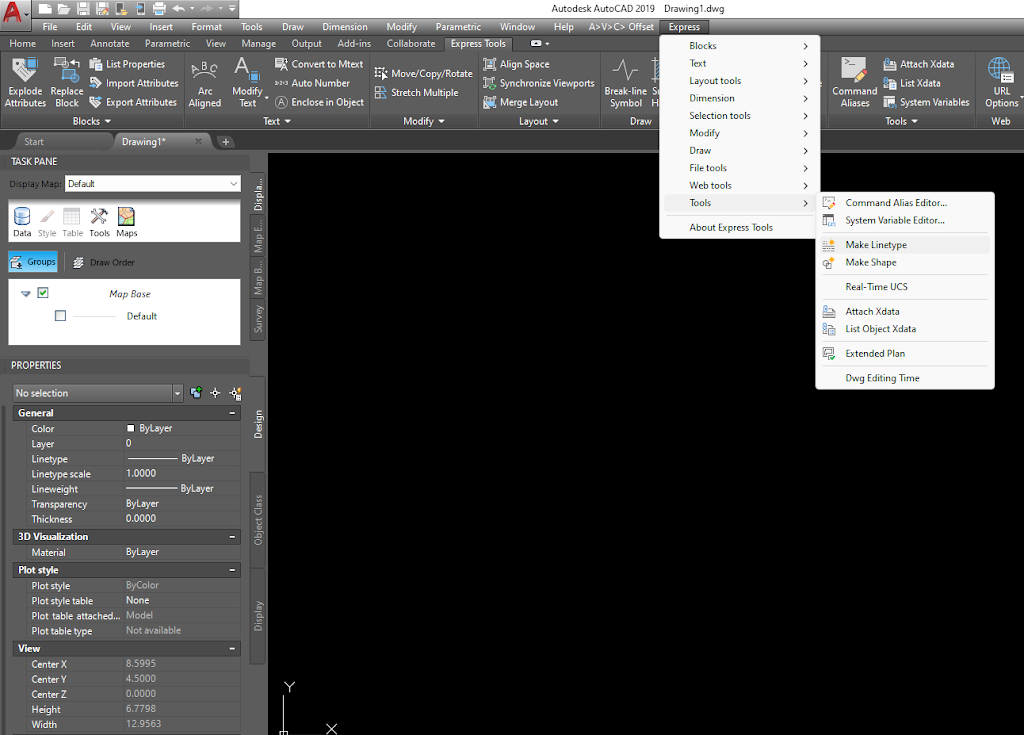
How To Create Custom Line Type
- Open a new or existing drawing in AutoCAD.
- Type “Linetype” in the command line and press enter. This will open the “Linetype Manager” dialog box.
- Click on the “Load” button to load an existing line type to use as a base for your new line type.
- Select the line type you want to use as a base and click on the “OK” button.
- In the “Linetype Manager” dialog box, click on the “Create” button to create a new line type.
- Enter a name for your new line type in the “Name” field.
- In the “Pattern” field, enter a series of numbers and symbols to create your custom line type. You can use various symbols such as hyphens, dots, and commas to create different line patterns.
- Once you have entered the pattern, click on the “OK” button to save your new line type.
- The new line type will now be available in the “Linetype Manager” dialog box and can be used in your drawing.
- To use the new line type, type “Linetype” in the command line and press enter. Select the new line type from the list and click on the “OK” button.
- Draw the object or feature using the new line type in your drawing.
In summary, creating a custom line type in AutoCAD involves loading an existing line type as a base, creating a new line type with a unique pattern of numbers and symbols, and saving the new line type for use in your drawing.
How To Create Custom Hatch Type
Hatching is a technique used in AutoCAD to fill an enclosed area with a pattern of lines, symbols, or solid colors. AutoCAD provides a range of default hatch patterns, but you may need to create your own custom hatch pattern for a specific design requirement. Here’s how to create a custom hatch type in AutoCAD:
- Open the drawing in which you want to create a custom hatch pattern.
- Type “hatch” in the command line and press enter. This will open the “Hatch and Gradient” dialog box.
- In the “Hatch and Gradient” dialog box, click on the “Custom” button.
- In the “Custom Pattern” dialog box, enter a name for your custom hatch pattern in the “Name” field.
- In the “Angle” field, enter the angle at which you want the hatch pattern to be drawn.
- In the “Scale” field, enter the scale at which you want the hatch pattern to be drawn. The scale represents the size of the hatch pattern relative to the drawing size.
- In the “Angle Units” field, select the units in which you want to measure the hatch pattern angle.
- In the “Pattern Type” section, select the type of pattern you want to use for your hatch pattern. You can choose from solid, gradient, or user-defined pattern types.
- If you choose the user-defined pattern type, click on the “Custom…” button to create a custom hatch pattern.
- In the “Edit Hatch Pattern” dialog box, draw the pattern you want to use for your hatch. You can use lines, arcs, circles, and other geometric shapes to create the pattern.
- Once you have created the pattern, select it and click on the “Add” button to add it to the hatch pattern list.
- Click on the “OK” button to save your custom hatch pattern.
- The new custom hatch pattern will now be available in the “Hatch and Gradient” dialog box for use in your drawing.
To use the new custom hatch pattern, select the area you want to fill with the hatch, type “hatch” in the command line, and press enter. In the “Hatch and Gradient” dialog box, select the custom hatch pattern from the list and click on the “OK” button.
In summary, creating a custom hatch pattern in AutoCAD involves entering the pattern parameters, selecting the pattern type, and creating the pattern using lines, arcs, circles, or other shapes. Once you have created the pattern, you can add it to the hatch pattern list and use it to fill areas in your drawing.
